Assignment 1: Capacitive Sensor
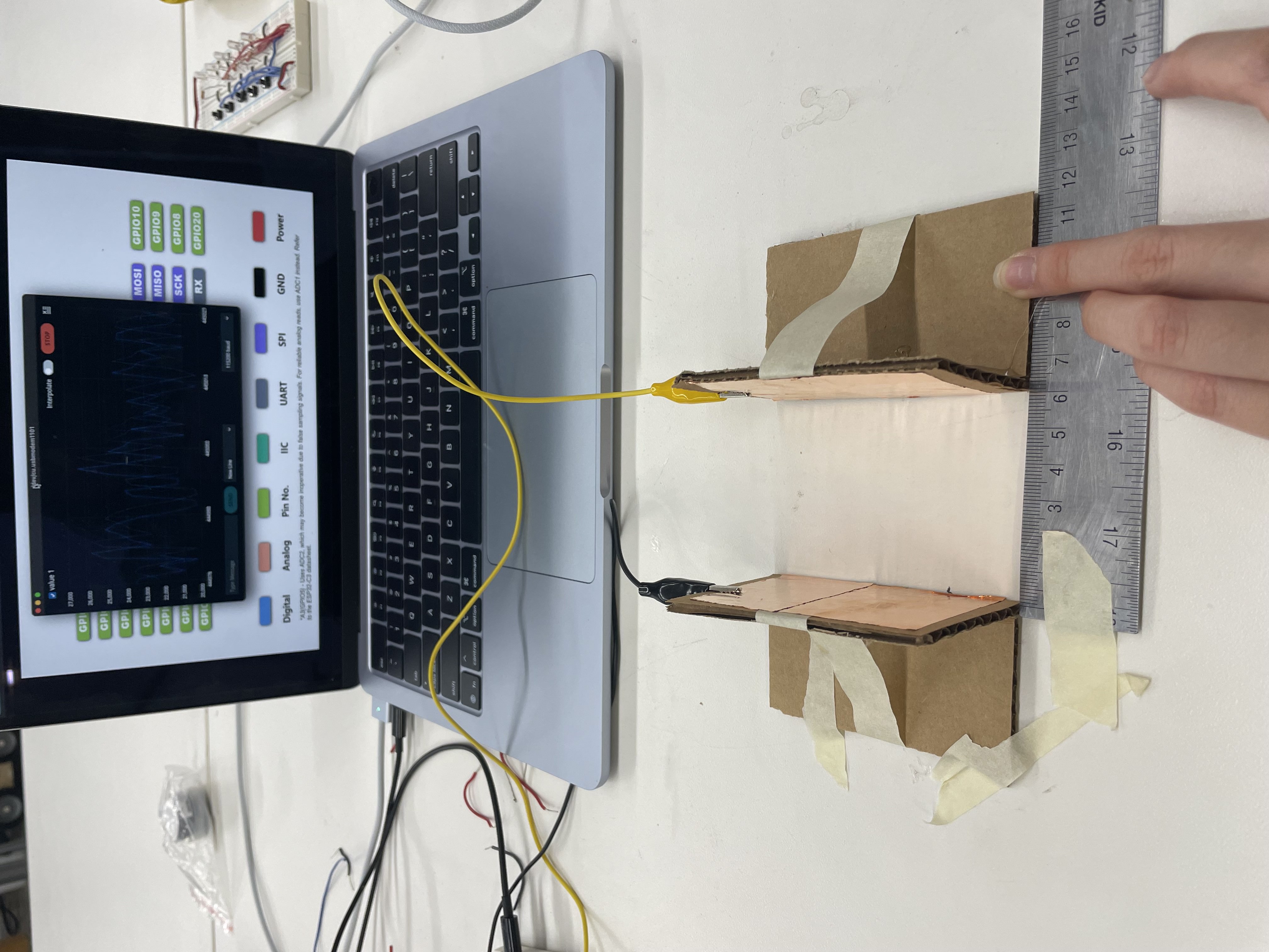
During class, my team was assigned to make a distance sensor. To make our capacitive sensor, we put capacitive tape on two pieces of cardboard and made a stand for each one. We then attached our sensors to a breadboard using alligator clips. I've recreated our sensors below:
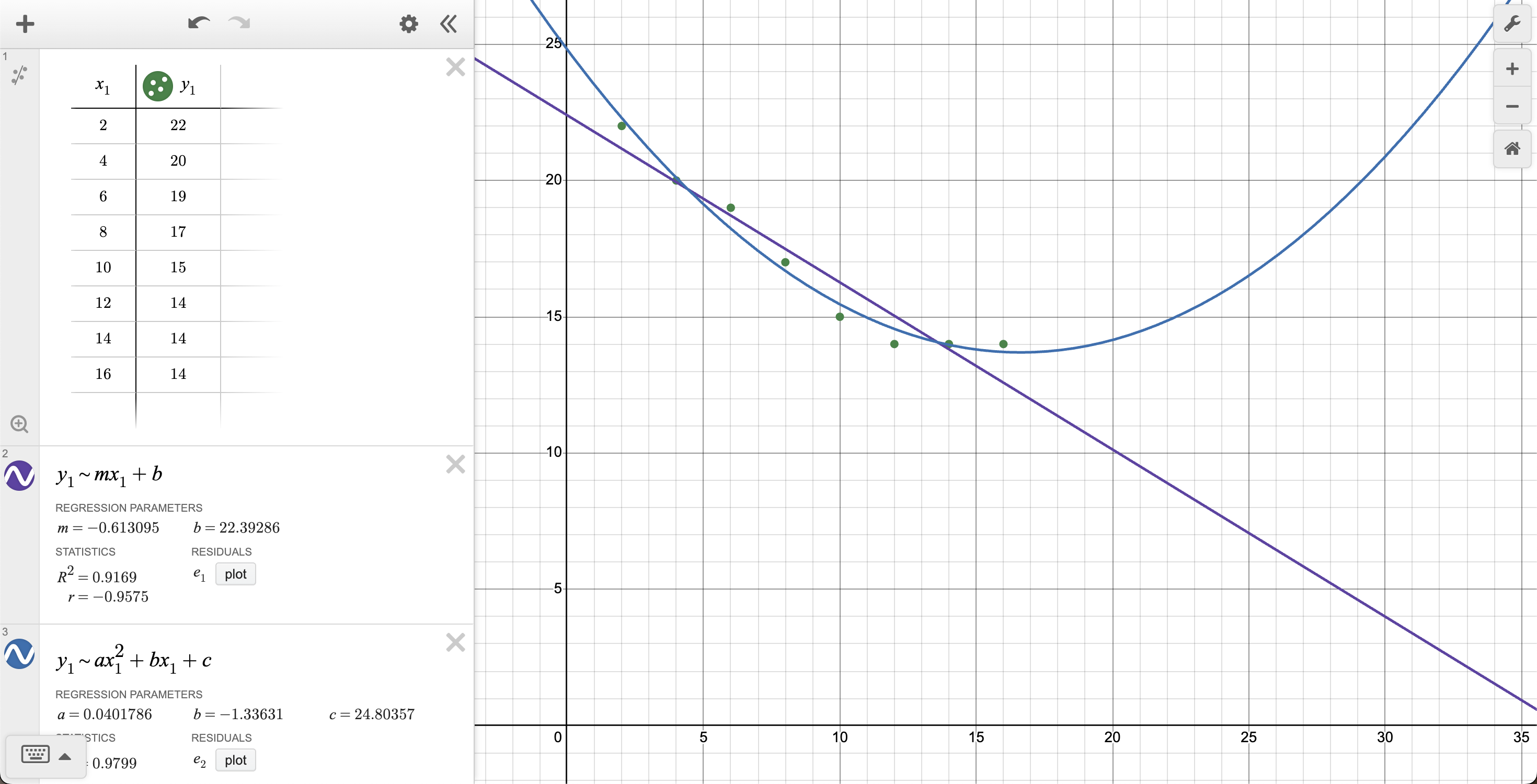
After, I recorded the values read by our sensors, plotted them on a graph, and found a line of best fit. Note: the x-values are in cm and the y-values are scaled down by 1,000 for graphing. After 14 cm, the read values started to plateau around 14,000 — likely the result of our capacitive sensors being too far apart to detect anything from one another.
Assignment 2: Another Sensor
I've made quite a few musically-inclined friends recently and they all have perfect pitch. Inspired by them (and to see if they really have perfect pitch), I wanted to use a microphone for my sensor. My idea was to record the frequency of a sound input (when the user clicks a button) and transcribe that frequency into its corresponding music note. The piezo buzzer then plays that frequency back to the user.
Materials
- ESP32 XIAO
- Adafruit SPW2430 MEMS Microphone
- PT-2726PQ Piezo Buzzer
- Button
- Breadboard
- Wires
The board
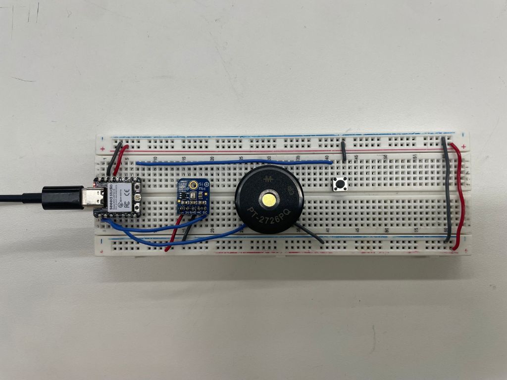
The first step was to make sure each individual component works. I wired up my breadboard and ran test code for the mic, piezo buzzer, and button to make sure each component was functional and wired properly.
Afterwards, I had to figure out how to record sound frequency accurately. Normally, the mic does not record the frequency of the sounds it picks up. To pick up frequency, I used the "arduinoFFT" library, which uses the Fast Fourier Transform (FFT) algorithm to detect the frequency of sound waves. I don't know exactly how the math works, but I implemented the library's functions using tutorials, examples, and searching online.
The code
double detectFrequency() {
    // Sample audio - collects 1024 readings every 250 ms
    for(int i = 0; i < SAMPLES; i++) {
        unsigned long start = micros();
        vReal[i] = analogRead(MIC_PIN);
        vImag[i] = 0; // Used for FFT math
        while(micros() - start < sampling_period_us);
    }

    // Remove DC offset
    double mean = 0;
    for(int i = 0; i < SAMPLES; i++) mean += vReal[i];
    mean /= SAMPLES;
    for(int i = 0; i < SAMPLES; i++) vReal[i] -= mean;

    // Run FFT
    FFT.windowing(vReal, SAMPLES, FFT_WIN_TYP_HAMMING, FFT_FORWARD);
    FFT.compute(vReal, vImag, SAMPLES, FFT_FORWARD);
    FFT.complexToMagnitude(vReal, vImag, SAMPLES);

    // Find dominant frequency
    double maxMag = 0;
    int maxIndex = 0;
    for(int i = 2; i < SAMPLES/2; i++) {
        if(vReal[i] > maxMag) { maxMag = vReal[i]; maxIndex = i; }
    }

    // Only return frequency if signal is strong enough
    if(maxMag > MAGNITUDE_THRESHOLD) {
        double y1 = vReal[maxIndex - 1];
        double y2 = vReal[maxIndex];
        double y3 = vReal[maxIndex + 1];
        double delta = 0.5 * (y3 - y1) / (2 * y2 - y1 - y3);
        double interpolatedIndex = maxIndex + delta;
        return (interpolatedIndex * SAMPLING_FREQUENCY) / SAMPLES;
    }
    return 0; // Signal too weak
}
Afterwards, I had to transcribe the frequency into its corresponding music note.
String frequencyToNote(double frequency) {
    if(frequency < 20) return "---";

    // A4 = 440 Hz is our reference (MIDI note 69)
    // n = 12 * log2(f / 440) + 69
    double noteNum = 12 * log(frequency / 440.0) / log(2) + 69;
    int nearestNote = round(noteNum);

    if(nearestNote < 0 || nearestNote > 127) return "Out of Range";

    int octave = (nearestNote / 12) - 1;
    int noteIndex = nearestNote % 12;
    return String(noteNames[noteIndex]) + String(octave);
}
From there, the code mostly involved getting the frequency to play back, taking input from the button, and printing output to the Serial monitor. For the full details, including helper functions and comments, see the file below:
↓ Frequency Sensor (.ino)Demo
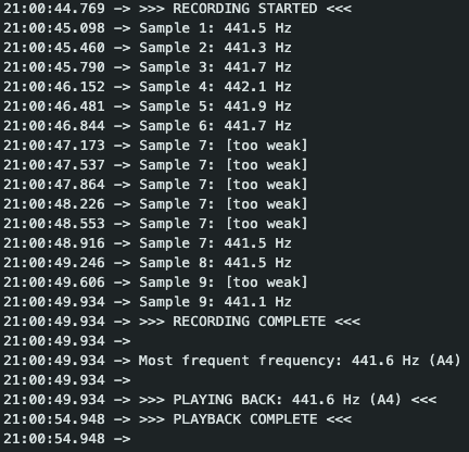
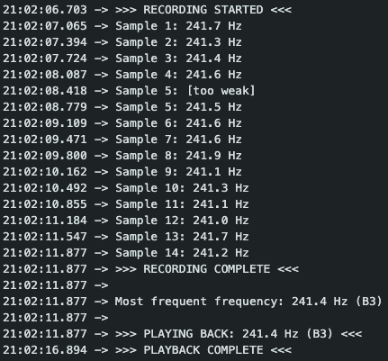
The recordings are generally pretty accurate. There is some variation in the number of samples since not all meet the threshold to be recorded.